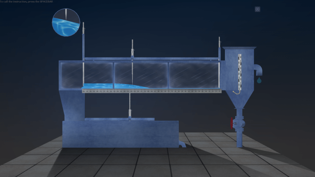
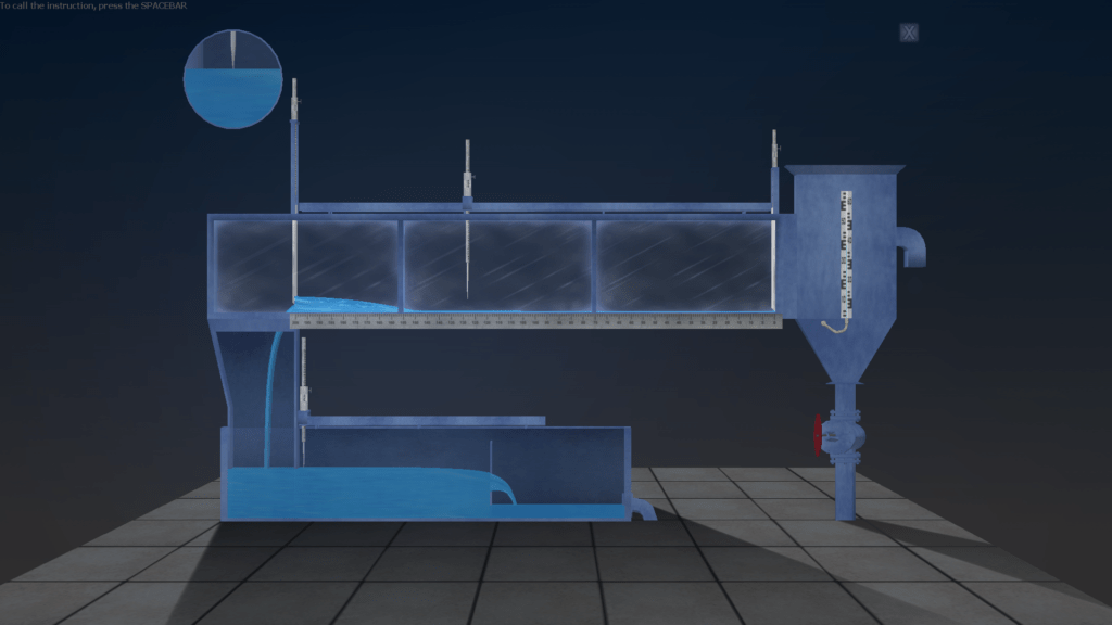
Software laboratory complex for the simulation of laboratory work on the main sections of the course of Open Channel Hydraulics for technical specialties. The program complex includes simulation labs:
The virtual laboratory practice is implemented in the form of graphical applications running under the MS Windows operating system.
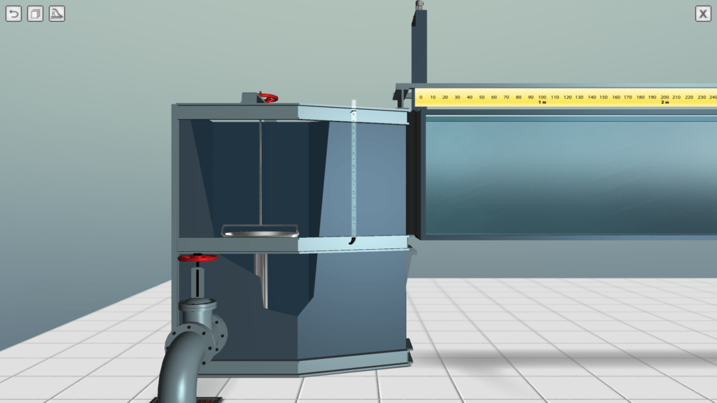


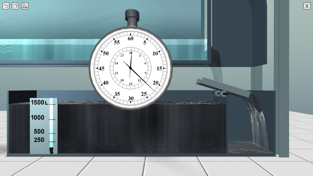
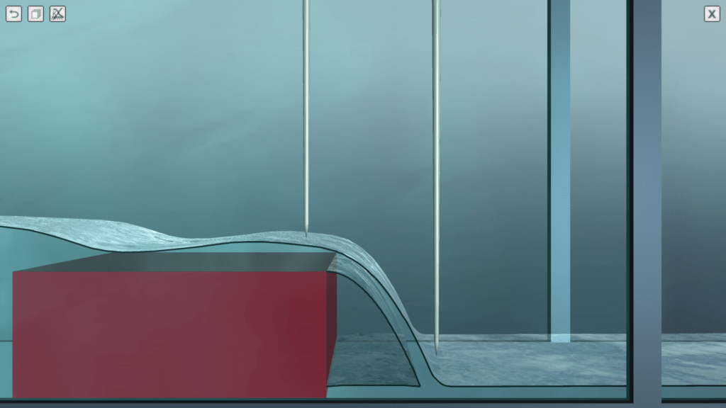
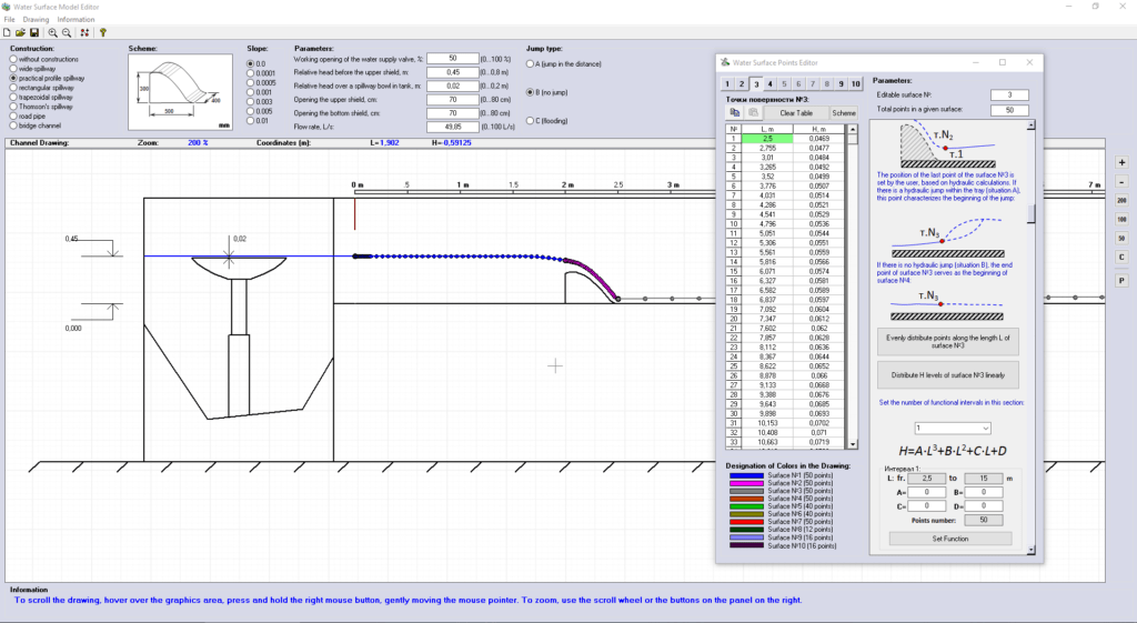
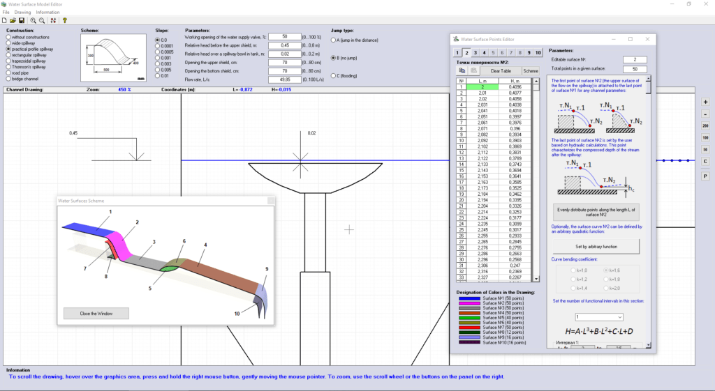
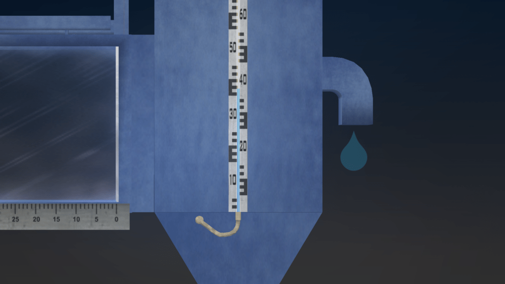
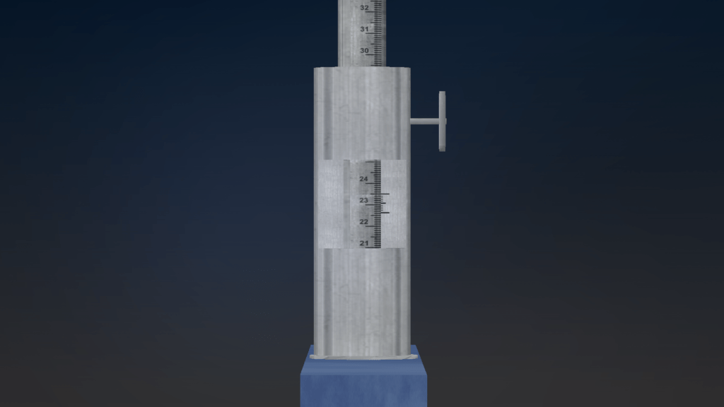
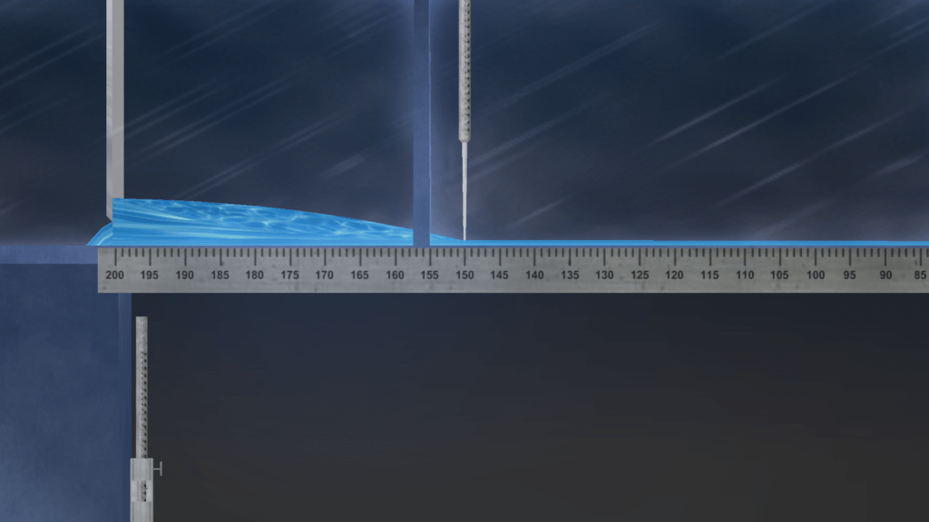
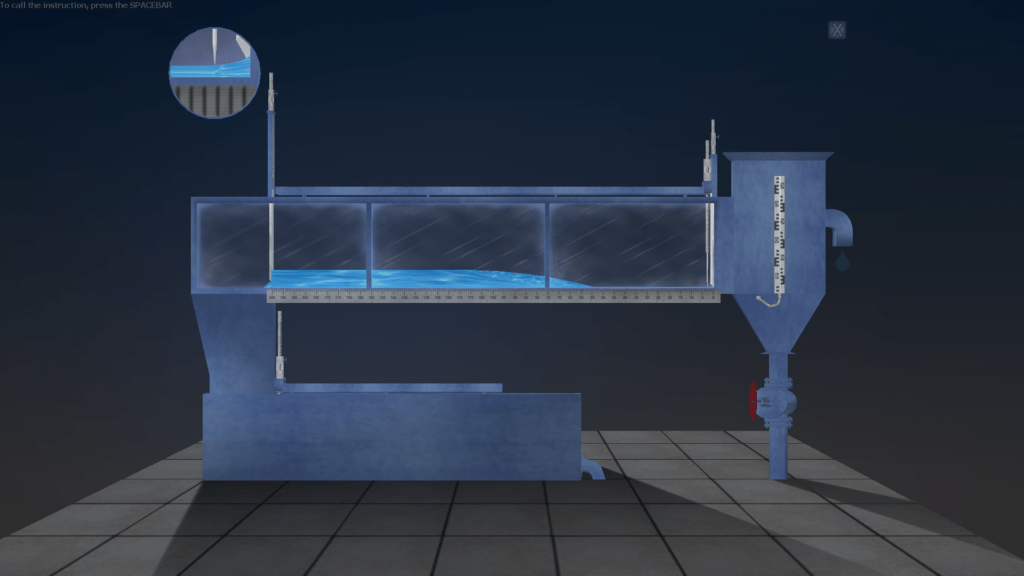
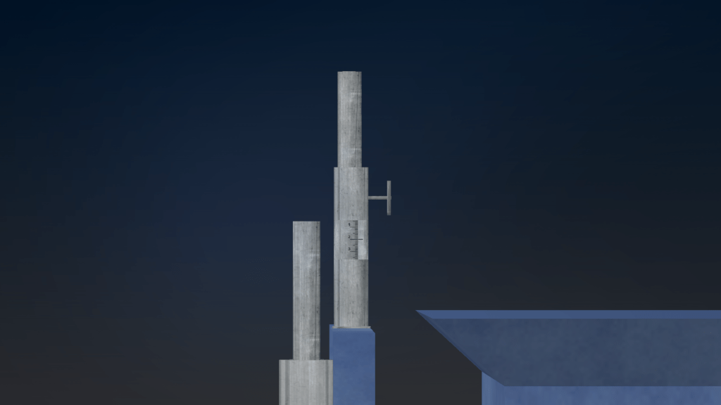
OBJECTIVE: The determination of the value of the roughness coefficient of the open channel of rectangular cross section by experimental data. SUMMARY: The laboratory stand is represented by a hydraulic channel 15 meters long, equipped with two flat closures, two measuring needles, a ruler, a lifting mechanism for setting the bottom slope, a pressure tower and a flow-measuring tank. Water flow in the system is measured using a stopwatch.
OBJECTIVE: The determination of the energy state of the water flow in the open channel and construction of the free surface curves using the experimental data; the determining the type and shape of the free surface flow curves according to the depth measurement data at various points along the length of the flow; the comparison of empirical data with theoretical and determination of discrepancy. SUMMARY: Laboratory work is carried out on a hydraulic channel 15 meters long, equipped with two flat closures, two measuring needles, a ruler, a lifting mechanism for setting the bottom slope, a pressure tower and a flow-measuring tank. Water flow in the system is measured using a stopwatch. In the process, the flow depth is measured along the entire length of the tray design.
OBJECTIVE: The experimentally determination for a rectangular weir with a thin wall of the flow coefficient and comparing it with a theoretical value. SUMMARY: Laboratory work is carried out on a hydraulic channel 15 meters long. At a given distance from the flat shield of the upper pool, a special design is installed in the channel ‒ a rectangular weir with a thin wall. The flow of water overflows through the weir, forming a free surface of a certain shape. With the help of measuring needles, the flow depths in the upper and lower pools are measured.
OBJECTIVE: The experimentally determination data for weirs with a wide threshold of the discharge coefficient and the flooding coefficient and their comparison with theoretical values; the construction the curves of the free surface flow on the experimental data. SUMMARY: Laboratory work is carried out on a hydraulic channel 15 meters long. At a specified distance from the flat shield of the upper pool, a special design is installed in the channel ‒ a weir with a wide threshold. The flow of water overflows through the weir, forming a free surface of a certain shape. With the help of measuring needles, the flow depths in the upper and lower pools are measured. Several models of flow flow are considered, including the situation with flooded overflow.
OBJECTIVE: The determination of the practical profile of the flow rate and the coefficient of flooding on the basis of experimental data for the weir and comparing them with theoretical values; measurement of the surface marks of the jet on the water discharge face at 4 points; the construction of the free flow surface profiles on the experimental data. SUMMARY: Laboratory work is carried out on a hydraulic channel 15 meters long. At a specified distance from the flat shield of the upper pool, a special design is installed in the channel – a weed of a practical profile. The flow of water overflows through the weir, forming a free surface of a certain shape. With the help of measuring needles, flow depths are measured in the upper and lower pools, as well as on the surface of the weir. Several models of flow are considered, including the situation with flooded overflow.
OBJECTIVE: The observation the free and non-free flow of the stream from under the shield to the horizontal rectangular channel; definition of the nature of the expiration; determination of flow coefficient and critical depth from experimental data. SUMMARY: Laboratory work is carried out on a hydraulic channel 15 meters long. Various flow patterns are considered.
OBJECTIVE: The study of hydraulic jump; measuring the parameters of the main elements of the jump and comparing them with theoretical values; the determination of energy loss in a hydraulic jump. SUMMARY: Laboratory work is carried out on a hydraulic channel 15 meters long. Various models of hydraulic jump are considered.
OBJECTIVE: The study the hydraulic jump and outflow from under the shield on the model of a short hydraulic channel. SUMMARY: Laboratory work is carried out on a hydraulic channel with a length of 2 meters. Various flow patterns are considered. The parameters of the laboratory setup are changed in real time. For measuring the flow of water in the lower part of the laboratory setup Thomson’s weir is provided.

